- 您现在的位置:买卖IC网 > Sheet目录17350 > IRDC3841W (International Rectifier)BOARD EVAL FOR IR3841W 8A CONV
�� �
�
�IR3841MPbF�
�Where:�
�Z� IN�
�V� OUT�
�R� 8�
�R� 3�
�C� POLE�
�C� 4�
�Z� f�
�V� in� =� Maximum� Input� Voltage�
�V� osc� =� Oscillator� Ramp� Voltage�
�F� o� =� Crossover� Frequency�
�F� ESR� =� Zero� Frequency� of� the� Output� Capacitor�
�F� LC� =� Resonant� Frequency� of� the� Output� Filter�
�R� 8� =� Feedback� Resistor�
�F� z� =� 0� .� 75� *�
�H(s)� dB�
�Gain(dB)�
�R� 9�
�Fb�
�V� REF�
�E/A�
�Comp�
�Ve�
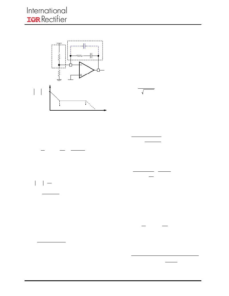
�To� cancel� one� of� the� LC� filter� poles,� place� the�
�zero� before� the� LC� filter� resonant� frequency� pole:�
�F� z� =� 75� %� F� LC�
�1�
�..........� ..........� ..........� .......� (22)�
�2� π� L� o� *� C� o�
�Use� equations� (20),� (21)� and� (22)� to� calculate�
�F�
�F� Z�
�POLE�
�Frequency�
�C4.�
�One� more� capacitor� is� sometimes� added� in�
�parallel� with� C4� and� R3.� This� introduces� one�
�more� pole� which� is� mainly� used� to� suppress� the�
�V� e� Z� 1� +� sR� 3� C� 4�
�F� P� =�
�..........� ..........� ..........� ...(23)�
�2� π� *� R� 3� *�
�H� (� s� )� =�
�R� 3�
�C� POLE� =�
�?�
�..........� ..........� ..(� 24� )�
�1� π� *R� 3� *F� s�
�Fig.� 14.� Type� II� compensation� network�
�and� its� asymptotic� gain� plot�
�The� transfer� function� (� V� e� /V� o� )� is� given� by:�
�=� H� (� s� )� =� ?� f� =� ?� .....� (18)�
�V� o� Z� IN� sR� 8� C� 4�
�The� (s)� indicates� that� the� transfer� function� varies�
�as� a� function� of� frequency.� This� configuration�
�introduces� a� gain� and� zero,� expressed� by:�
�.........� ..........� ..........� .........� (19)�
�R� 8�
�switching� noise.�
�The� additional� pole� is� given� by:�
�1�
�C� 4� *� C� POLE�
�C� 4� +� C� POLE�
�The� pole� sets� to� one� half� of� the� switching�
�frequency� which� results� in� the� capacitor� C� POLE� :�
�1� 1�
�π� *R� 3� *F� s� ?�
�C� 4�
�For� a� general� solution� for� unconditional� stability�
�F� z� =�
�1�
�2� π� *� R� 3� *� C� 4�
�..........� ..........� ........� (20)�
�for� any� type� of� output� capacitors,� and� a� wide�
�range� of� ESR� values,� we� should� implement� local�
�feedback� with� a� type� III� compensation� network.�
�V� e� Z� f�
�First� select� the� desired� zero-crossover� frequency�
�(� F� o� ):�
�F� o� >� F� ESR� and� F� o� ≤� (� 1/5� ~� 1/10� )� *� F� s�
�Use� the� following� equation� to� calculate� R3:�
�The� typically� used� compensation� network� for�
�voltage-mode� controller� is� shown� in� figure� 15.�
�Again,� the� transfer� function� is� given� by:�
�=� H� (� s� )� =� ?�
�V� o� Z� IN�
�V� in� *� F� LC�
�?� C� *� C� 3� ?� ?�
�?� C� 4� +� C� 3� ?� ?� ?�
�R� 3� =�
�V� osc� *� F� o� *� F� ESR� *� R� 8�
�2�
�..........� ..........� .......� (21)�
�By� replacing� Z� in� and� Z� f� according� to� figure� 15,�
�the� transfer� function� can� be� expressed� as:�
�(� 1� +� sR� 3� C� 4� )� [� 1� +� sC� 7� (� R� 8� +� R� 10� )� ]�
�H� (� s� )� =� ?�
�?�
�sR� 8� (� C� 4� +� C� 3� )� ?� 1� +� sR� 3� ?� 4� ?� ?� (� 1� +� sR� 10� C� 7� )�
�?� ?�
�....� (25)�
�06/18/09�
�20�
�发布紧急采购,3分钟左右您将得到回复。
相关PDF资料
TARQ474M035
CAP TANT 0.47UF 35V 20% AXIAL
GCM06DCCN-S189
CONN EDGECARD 12POS R/A .156 SLD
A9CAA-0803E
FLEX CABLE - AFK08A/AE08/AFH08T
A9BBA-1002E
FLEX CABLE - AFJ10A/AE10/AFJ10A
GCM06DCCH-S189
CONN EDGECARD 12POS R/A .156 SLD
EEM15DSXI
CONN EDGECARD 30POS DIP .156 SLD
GCM06DCCD-S189
CONN EDGECARD 12POS R/A .156 SLD
SJP7401-4-50-BLACK
LOOP BLACK 4" X 50YD X 0.11"
相关代理商/技术参数
IRDC3842
功能描述:电源管理IC开发工具 IR3842 SYNC CONV 600kHz EVAL BRD RoHS:否 制造商:Maxim Integrated 产品:Evaluation Kits 类型:Battery Management 工具用于评估:MAX17710GB 输入电压: 输出电压:1.8 V
IRDC3842A
功能描述:电源管理IC开发工具 IR3842A SYNC CONV 300kHz EVAL BRD RoHS:否 制造商:Maxim Integrated 产品:Evaluation Kits 类型:Battery Management 工具用于评估:MAX17710GB 输入电压: 输出电压:1.8 V
IRDC3842W
功能描述:电源管理IC开发工具 User Guide IR3842W Eval Brd RoHS:否 制造商:Maxim Integrated 产品:Evaluation Kits 类型:Battery Management 工具用于评估:MAX17710GB 输入电压: 输出电压:1.8 V
IRDC3843
制造商:International Rectifier 功能描述:BOARD EVALUATION IR3843
IRDC3843A
功能描述:电源管理IC开发工具 IR3843 SYNC CONV 600kHz EVAL BRD RoHS:否 制造商:Maxim Integrated 产品:Evaluation Kits 类型:Battery Management 工具用于评估:MAX17710GB 输入电压: 输出电压:1.8 V
IRDC3843W
功能描述:电源管理IC开发工具 User Guide IR3843W Eval Brd RoHS:否 制造商:Maxim Integrated 产品:Evaluation Kits 类型:Battery Management 工具用于评估:MAX17710GB 输入电压: 输出电压:1.8 V
IRDC3853
功能描述:电源管理IC开发工具 User Guide IR3853 Eval Brd RoHS:否 制造商:Maxim Integrated 产品:Evaluation Kits 类型:Battery Management 工具用于评估:MAX17710GB 输入电压: 输出电压:1.8 V
IRDC3853 - SUPIRBUCK
制造商:International Rectifier 功能描述:INTERNATIONAL RECIFIER - GEN 2.1 SUPIRBUCK FAMILY - Bulk